Understanding VIDC colours and bank-switching on the Archimedes
For those of us who are more used to the character-based screen modes of the BBC Micro, the Archimedes screen mode used in Lander is, at first glance, an absolute joy to work with.
On the BBC Micro, the screen is split up into character blocks of eight stacked bytes, so to draw something as simple as a horizontal line, the calculations are surprisingly involved. And it gets even more challenging if you opt to use one of the four-colour or eight-colour screen modes.
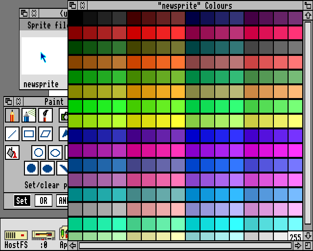
The Archimedes is a lot simpler and does away with the concept of character blocks altogether: instead, screen memory is very logical in its layout. This is particularly true in the 256-colour mode that Lander uses. I mean, look at all these colours:
For those of us graduating to the Archimedes from the eight-colour BBC Micro, this was pretty mind-blowing stuff.
Let's start by looking at this improved screen memory structure, and then take a look at the weird and wonderful world of VIDC colour numbers (VIDC being the video controller chip).
Screen memory
-------------
Lander uses screen mode 13 with shadow memory enabled, so it actually uses mode 141, which is 128 + 13, as adding 128 to an Archimedes mode number adds an extra bank of screen memory. Mode 13 is 320 pixels wide and 256 pixels high, with 256 colours available for each pixel. The range of 256 colours comes from the default VIDC palette, which we'll talk about briefly at the end of this article, but for this part of the discussion the important point is that each pixel takes up one byte, with that byte containing a colour number from 0 to 255 that describes that pixel's colour.
Screen memory is arranged as you would think it would be: each row of 320 pixels corresponds to a row of 320 bytes in memory. It's that simple - there are no character blocks or separate colour memories here, it's just a really simple, easy-to-follow memory structure. The 320x256 screen takes up a total of 320 * 256 = &14000 bytes, and we can convert an (x, y) screen coordinate into a memory location as follows:
start of screen memory + (320 * y) + x
The origin at (0, 0) is in the top-left corner of the screen, so this simply skips 320 bytes for each y-coordinate that we move down the screen, and then adds x bytes to move along that row to the correct x-coordinate.
This calculation can be done in three lines of ARM code. If Rx and Ry contain the (x, y) screen coordinate, and Rs contains the address of the start of screen memory, then we can calculate the address of the pixel's screen memory into Ra like this:
  ADD     Ra, Rs, Rx                \ Set Ra = Rs + Rx
                                    \        = screenAddr + x-coordinate

  ADD     Ry, Ry, Ry, LSL #2        \ Set Ra = Ra + ((Ry + Ry << 2) << 6)
  ADD     Ra, Ra, Ry, LSL #6        \        = Ra + ((Ry + 4 * Ry) * 64)
                                    \        = Ra + 320 * Ry
                                    \        = screenAddr + x-coordinate
                                    \          + 320 * y-coordinate
                                    \
                                    \ So Ra contains the screen address of the
                                    \ coordinate in screen memory
You'll see this approach dotted throughout the Lander source, and another common idiom is adding 320 to a screen address to move down to the same point on the next pixel line down.
Finally, Lander stores the start of screen memory in the screenAddr variable, but note that it actually stores the address of the first pixel line below the score bar, as that's the start of the screen memory where we draw graphics (the top two lines are purely used for text). As there are 16 pixel lines in the score bar, screenAddr contains the 17th pixel line down, at the start of screen memory plus 16 * 320.
Screen banks
------------
As mentioned above, Lander uses mode 13 with shadow memory enabled. This means the operating system reserves two separate screen's worth of memory in two separate screen banks - screen bank 1 and screen bank 2.
In Arthur, RISC OS 2 and RISC OS 3 up to version 3.11, the addresses of these two banks are predictable, as the operating system always puts them at the top end of the memory map. The top of memory is at &02000000, so given that each screen bank takes up &14000 bytes, we know that bank 1 is at &01FD8000 and bank 2 is at &01FEC000. These addresses are hardcoded into Lander in the screenBank1Addr and screenBank2Addr variables, which also include the additional 16 * 320 bytes to skip the score bar. See the Lander memory map for details on how screen memory fits in with the rest of the memory map.
In RISC OS 3.5 and later, the operating system decides where to place screen memory, so Lander won't work on those operating systems without modification, as the hardcoded values in the source no longer point to the correct locations.
So why do we want two screen banks? It's to remove flicker from the game's graphics. Elite is famous for the amount of flicker it displays on the BBC Micro; it's caused by the wireframe redraw routines, which erase and redraw each on-screen wireframe using EOR logic. This means we get to see ship wireframes disappear and then reappear on each frame, giving the game its characteristic flicker (for more about this issue, and how it can be fixed, see the deep dive on flicker-free ship drawing in my Elite project).
With two screen banks, we can show one bank to the user while we do all the erasing and drawing in the other bank, and when we've finished, we can swap the banks around, which flips the screen to show the next frame in the animation without any visible drawing - it's instant. This also means we can simply clear down the entire frame once it's no longer visible, and then draw the entire scene from scratch; there is no need for the line-by-line erasing and redrawing of Elite.
The operating system provides two system calls to change the screen banks, and the SwitchScreenBank routine does exactly this at the end of each iteration of the main loop, after all the graphics have been drawn. The OS_Byte 113 call tells the operating system which screen bank to display, and the OS_Byte 112 call tells the operating system which screen bank its routines should write to (which we need to do for the score bar, as we update the scores using the operating system's own OS_WriteC routine). Meanwhile, we set the screen address in screenAddr to the relevant address for the hidden screen bank, choosing the correct address from screenBank1Addr or screenBank2Addr. This means that screenAddr always points to screen memory for the hidden screen bank, which is where we draw the next frame.
We than wait for the vertical sync, to make sure that the screen has indeed switched to the new bank, and then the same routine clears down the newly hidden bank by simply filling the part below the score bar with zeroes (which represent black). This makes the hidden bank ready for drawing the next frame.
This switching process happens every iteration around the main loop, and results in some very smooth graphics indeed.
VIDC colour numbers
-------------------
The final piece of the puzzle is the format of the colour bytes that we poke into screen memory. Lander uses the default Archimedes palette, which provides us with 256 colours to choose from. But how do these colours work?
In an ideal world, we would like to be able to display RGB colours, with each of the three channels supporting four bits of brightness (0 to 15). But that would require 12 bits of colour data, and we only have eight, so the default palette supports an encoding process that drops four of those bits to enable us to encode an RGB colour into a single byte.
Given three channel values - red, green and blue - with each value in the range 0 to 15 (for four bits), we can encode these channels into a VIDC colour number as follows:
- Bit 7 = blue bit 3
- Bit 6 = green bit 3
- Bit 5 = green bit 2
- Bit 4 = red bit 3
- Bit 3 = blue bit 2
- Bit 2 = red bit 2
- Bit 1 = sum of red/green/blue bit 1
- Bit 0 = sum of red/green/blue bit 0
The sums for bits 0 and 1 are done using logical OR, so the value of a bit will be 1 if any of the red, green or blue channels have that bit set.
This colour number is actually the number of an entry in the default palette, but as we are not changing the palette, it's easier just to think of this as a colour number. Note that this encoding only applies to the default palette; the VIDC palette is programmable, but it's a pretty challenging process, and thankfully Lander doesn't go there.
You can see the default palette in the Paint application in the screenshot at the start of this article; here it is again:
Within this palette, bits 0 and 1 can be thought of as a tint value in the range 0 to 3, with bits 2 to 7 defining the base colour in the range 0 to 63. In other words the default palette consists of 64 colours, each of them in four tints, so although mode 13 is a 256-colour mode, it is more accurate to call it a 64-colour mode with four tint levels.
You can see this construction of VIDC colour numbers throughout the Lander code; as with the inline multiplication algorithms, I suspect the colour algorithms were inserted into the code using macros, as they are identical apart from the registers that are used. Picking just one example of many, the SetParticleColourToFade routine sets the colour of a spark particle so that it fades from white to red over the particle's lifespan, and it does this by calculating the three channel values of the desired colour, with R0 for red, R1 for green and R2 for blue, and then combining these values into the format above to get the colour byte.
It's worth reiterating that mode 13 has one byte per pixel. This means that a lot of screen drawing is done using the byte storage command STRB, to set just one pixel, but some routines, like the horizontal line-drawing routine at DrawHorizontalLine, take advantage of the fact that poking a whole word into memory will set four pixels in one shot (though this optimisation is only used by longer lines; shorter lines still use STRB, interestingly). For more on this, see the deep dive on drawing triangles, as all the 3D objects are actually made up of horizontal lines, with each line being no more than a sequence of VIDC colour numbers.