Storing 3D object definitions using vertices, faces and normals
The world of Lander is composed of three parts: the rolling landscape, the 3D objects, and the particle system. In this deep dive we're going to take a look at Lander's 3D objects and how they are defined.
Consider the following scene:
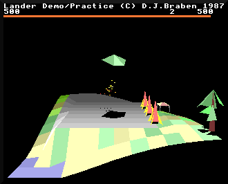
This familiar take-off scenario contains the landscape, with its flat grey launchpad, a hint of sea in the bottom-left corner, and gently sloping green fields. There's a cloud of exhaust particles below the player's ship, and the rest of the scene is made up of 3D objects. There's the ship itself, then the three rockets along the right edge of the launchpad, a gazebo hiding in the distance, and a tall leafy tree on the right.
That isn't all, though, as the ship, tree and rockets all cast shadows on the ground (and so does the gazebo, but its shadow merges into the background, so isn't terribly obvious). The shadows are drawn as part of the 3D object system, so check out the deep dive on drawing 3D objects for more details.
But for this article, let's start with a look at the different flavours of in-game object, before moving on to the data structures that define those objects.
Object designs
--------------
There are 13 object designs in Lander, but one of them, the pyramid, is unused and never appears in-game. Each design has an associated blueprint, which we'll look at below.
The different objects are as follows, with all of them shown to the same scale:
| Name and blueprint | Object attributes | Object |
|---|---|---|
| Player's ship objectPlayer |
|  |
| Tall leafy tree objectTallLeafyTree |
|  |
| Smoking remains that bend to the left objectSmokingRemainsLeft |
|  |
| Small leafy tree objectSmallLeafyTree |
|  |
| Smoking remains that bend to the right objectSmokingRemainsRight |
|  |
| Fir tree objectFirTree |
|  |
| Building objectBuilding |
|  |
| Smoking remains of a building objectSmokingBuilding |
|  |
| Gazebo objectGazebo |
|  |
| Smoking remains of a gazebo objectSmokingGazebo |
|  |
| Rocket objectRocket |
|  |
| Rock objectRock |
|  |
| Pyramid (unused) objectPyramid |
| 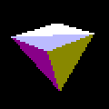 |
Some objects represent destroyed versions of other objects - see the deep dive on placing objects on the map for details of how these objects are managed, and the particles and particle clouds article for information on how objects get destroyed.
Most objects are designed to sit on the landscape; only the player's ship and rock are designed to be airborne.
Object blueprints
-----------------
Much like Elite, each 3D object in Lander has an associated blueprint that contains all the data required to draw that object. In Elite these are known as the ship blueprints, but for Lander we'll call them object blueprints, as they cover quite a range of designs.
Each object blueprint starts with four 32-bit words that define the data structure, as follows:
| Word | Content |
|---|---|
| Word #0 | Number of vertices |
| Word #1 | Number of faces |
| Word #2 | Offset from the start of the blueprint to the face data |
| Word #3 | Object flags:
|
The next batch of data, starting at word #4, is the vertex data. Each vertex in the object's shape is stored as a three-word (x, y, z) coordinate, like this:
| Word | Content |
|---|---|
| Word #4 | Vertex 0 x-coordinate |
| Word #5 | Vertex 0 y-coordinate |
| Word #6 | Vertex 0 z-coordinate |
| Word #7 | Vertex 1 x-coordinate |
| Word #8 | Vertex 1 y-coordinate |
| Word #9 | Vertex 1 z-coordinate |
| Word #10 | Vertex 2 x-coordinate |
| ... | ... |
This continues until we reach the last vertex, which is followed by the face data, starting at the offset defined in word #2. The face data is rather more involved, as each face has seven words of data (with four bytes in each of those words), giving a data structure like this:
| Word | Content |
|---|---|
| Offset | Face 0 normal x-coordinate |
| Offset + 1 * 4 | Face 0 normal y-coordinate |
| Offset + 2 * 4 | Face 0 normal z-coordinate |
| Offset + 3 * 4 | Face 0 vertex number 1 |
| Offset + 4 * 4 | Face 0 vertex number 2 |
| Offset + 5 * 4 | Face 0 vertex number 3 |
| Offset + 6 * 4 | Face 0 colour, in the format &rgb |
| Offset + 7 * 4 | Face 1 normal x-coordinate |
| Offset + 8 * 4 | Face 1 normal y-coordinate |
| Offset + 9 * 4 | Face 1 normal z-coordinate |
| ... | ... |
This continues until we reach the end of the face data, and the end of the object blueprint.
Note that because of the way objects are drawn, rotating objects have to be convex and fully closed. Static objects can be open - the gazebo is a good example - but the rule for static objects is that their faces must be ordered so the faces at the back of the object appear first in the blueprint, and then the faces at the front. This ensures they are drawn in the correct order, from back to front.
When combined with the object's orientation, the object blueprint contains all the design data that we need to draw that object. See the deep dive on drawing 3D objects for the details of the drawing process.