Converting a set of altitudes into an undulating landscape of coloured tiles
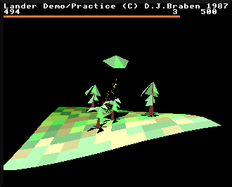
The landscape in Lander is arguably the game's killer feature, giving the game a real sense of three-dimensional depth. The deep dive on generating the landscape explains how the shape of this landscape is procedurally generated using Fourier synthesis, and in this deep dive we'll take a look at the more prosaic process of converting those mathematical results into an undulating on-screen landscape like this:
Before we get stuck in, note that the landscape-drawing process is interwoven with the object-drawing process, to ensure that objects appear on top of the landscape and don't get obscured by undulations or objects that are further away from the viewer. To keep things simple we'll skip over the object-drawing process in this article, but you can read all about the latter in the deep dive on depth-sorting with the graphics buffers.
First, we need to define some terminology, so we can talk about the different parts of the landscape without getting stuck. Specifically we need to understand the landscape tile grid, which we'll discuss next, and you might also like to read the deep dive on the camera and the landscape offset, as we will be referring to both of these concepts below.
The landscape tile grid
-----------------------
As you can see from the above screenshot, the landscape is made up of square tiles (though we'll talk a bit more what we mean by "square" in a moment). These tiles form rows that run from left to right across the screen, and they form columns they run in and out of the screen. Where four tiles meet there is a tile corner.
In terms of the source code, the landscape in Lander is defined as being 13 tile corners wide, giving 12 full tiles from side to side, and it is 11 tile corners deep, giving 10 full tiles from front to back. These values are defined in the TILES_X and TILES_Z configuration variables, which represent the tile corner count along the x-axis (left to right) and z-axis (into the screen) respectively.
Lander draws the landscape in whole tiles only. This means that as the landscape moves under the player's ship, tiles appear and disappear at the edges of the 12 x 10 tile grid. In Zarch this process is smoothed out so the edges of the landscape are filled in by partial tiles, but in Lander only whole tiles are drawn, so the process is quite a bit clunkier than in the later, more sophisticated game.
But are these tiles always square? Well, the landscape tiles are a fixed square size in terms of the horizontal ground plane defined by y = 0 (the xz-plane) - in other words, if you picture the landscape as a paper map going into the screen, then the tiles are square in terms of the landscape's longitude and latitude. Of course, in three dimensions, steep parts of the landscape will have tiles with stretched edges that are much greater than the tile size, such as those along the front edge of the launchpad:
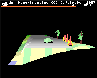
There is only one row of tiles along the front of the launchpad, but those tiles are very long. If you looked straight down at this scene from above, these tiles would look square and the landscape would look like a chess board, as the x- and z-coordinates of the tile corners are spaced out evenly, as specified by the configuration variable TILE_SIZE. The y-coordinates - the altitudes - vary wildly, but the underlying grid on the xz-plane is fixed, and it's this grid that we are going to iterate through as we draw the landscape one tile at a time, going from the back-left corner, along each row of tile corners from left to right, and moving forwards through the rows, drawing the landscape as we go.
Drawing the tiles
-----------------
Now that we know about the tile grid, let's look at how the landscape is actually drawn.
The drawing process is implemented by the DrawLandscapeAndBuffers routine, which is called towards the end of the main loop on every iteration (see the deep dive on the main game loop for details). As the routine name suggests, it draws both the landscape and the contents of the graphics buffers. The buffers contain all the on-screen 3D objects and particles, which is covered in the deep dive on depth-sorting with the graphics buffers, but for now let's just look at the process for drawing the landscape.
The landscape is drawn one tile row at a time, starting at the back left corner and working from left to right then back to front, but in terms of the drawing process, we actually work along the rows of tile corners rather than tiles. The DrawLandscapeAndBuffers routine contains two loops - an inner loop for working along each row and an outer loop for stepping through each of the rows from back to front - and in each case these loops iterate through tile row corners, not tiles. Part 1 of the routine sets up the variables we need in order to iterate across the landscape, and the two loops are in part 2 and part 3 (part 4 is only concerned with drawing the graphics buffers, so we'll ignore that part here).
The most important initial calculation is to work out the coordinates of the far left tile corner of the landscape, as this is our starting point. This calculation is simple enough; we simply take the camera position, which is at the centre-back of the landscape, and round it down to the nearest whole tile to the left, and then subtract the x-coordinate of the landscape offset to move to the left by half the landscape width. This gives us the starting corner in 3D world coordinates, snapped to the nearest tile corner to the far-left corner of the landscape.
Note that we only need to do this calculation in the x-axis and z-axis, as we're going to work our way through the coordinates of the underlying grid of tile corners, ignoring the landscape height at this point.
Before describing the drawing process in detail, let's consider the landscape grid for the on-screen landscape. Viewing the landscape from above, it looks like this, where the top-left corner shown below is the far-left corner of the visible landscape (i.e. the coordinate we just calculated):
     0    1    2    3    4    5    6    7    8    9   10   11   12

  a  +----+----+----+----+----+----+----+----+----+----+----+----+
     |    |    |    |    |    |    |    |    |    |    |    |    |
     |    |    |    |    |    |    |    |    |    |    |    |    |
  b  +----+----+----+----+----+----+----+----+----+----+----+----+
     |    |    |    |    |    |    |    |    |    |    |    |    |
     |    |    |    |    |    |    |    |    |    |    |    |    |
  c  +----+----+----+----+----+----+----+----+----+----+----+----+
     |    |    |    |    |    |    |    |    |    |    |    |    |
     :    :    :    :    :    :    :    :    :    :    :    :    :

     :    :    :    :    :    :    :    :    :    :    :    :    :
     |    |    |    |    |    |    |    |    |    |    |    |    |
  k  +----+----+----+----+----+----+----+----+----+----+----+----+
Let's label the corners in each 12-tile corner row from 0 to 12 going left to right, and let's label the rows from a through to k for the 10 tile rows. To draw this landscape, we will iterate through corners a0, a1, a2 and so on to a12, and then we'll move down to corners b0, b1, b2 and on to b12, and then c0 through c12, and so on until we get to k12 and the landscape is drawn.
As we work along each row of tile corners, we call the GetLandscapeAltitude routine with each corner's (x, z) world coordinate. This gives us the altitude of the landscape at that corner - i.e. the y-coordinate of that grid point on the landscape - and we project that 3D coordinate onto the 2D screen using the ProjectVertexOntoScreen routine. This gives us the screen coordinates of that point on the landscape; see the deep dive on projecting onto the screen for details on how the projection routine works.
We then store this projected coordinate in a block of memory called the corner store. There are two corner stores, cornerStore1 and cornerStore2, which we swap between after finishing each tile row, so at any one point one corner store is being used to store the coordinates from this row, and the other contains the coordinates that we stored when processing the previous row. As we work our way from a0 to a12 on the very first corner row at the back of the visible landscape, there is no previous row to consider, so all we do is work our way along, filling up the corner store with projected screen coordinates until we reach the end.
On the second row, from b0 to b12, things get more interesting. We start with the first corner, b0, and we go through the same process of calculating the altitude, projecting the result into screen coordinates, and storing that result in the corner store. We also fetch the coordinates of the corresponding corner from the previous row, a0, which we stored in the corner store on the last iteration. We stash both these coordinates (a0 and b0) in another variable, previousColumn, before moving along to the second corner on the second row, b1.
Again, we calculate the altitude of this corner, project it into screen coordinates and stash it in the corner store. We also fetch the coordinates of the corresponding corner from the previous row, a1, and store the coordinates of a1 and b1 into previousColumn, but when we do the last step, we also retrieve the values that were already in previousColumn (i.e. a0 and b0). So, at last, we have the four screen coordinates of the first tile - a0 and b0 from previousColumn, a1 from the corner store and b1 from the latest altitude calculation. We can now call the GetLandscapeTileColour routine to get the colour of this tile (which we'll talk about in the next section) and then we can call the DrawQuadrilateral routine to actually draw the tile, which itself calls the DrawTriangle routine twice to draw our rectangular tile as two triangles (see the deep dive on drawing triangles for details).
This process continues as we work along the tile row, so the next tile gets drawn from corners a1 and b1 (from previousColumn), a2 (from the corner store) and b2 (from the latest altitude calculation)... and so on, until we reach the end of the row and double back to start working along the next corner row from c0 onwards. And eventually we reach corner k12 and draw the last tile, and at that point we have finished drawing the landscape.
This process ensures that tiles towards the front are drawn later than tiles at the back. All tiles are drawn, even those that are facing away from us - unlike with the 3D objects, we do not work out tile visibility when drawing the landscape. There is a reason for this. Sometimes, if we're flying particularly low over hilly territory, we can get a glimpse of the underneath the landscape, like this:
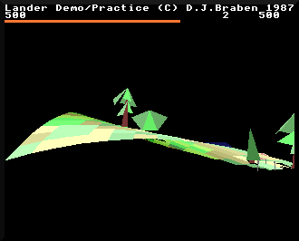
The part on the right is the underneath of the landscape, and if we didn't draw it, then the landscape would simply disappear for entire sections. That would look awful, so instead we always draw every landscape tile, and rely on the drawing order to ensure that it looks correct. Objects on top of the landscape at this point don't look great (like the gazebo to the right in the above screenshot), but when you're flying this low over hilly terrain, I'm not sure you're paying that much attention to the finer points of the drawing algorithm...
Tile colours
------------
We mentioned above that we fetch the colour of each tile that we draw by calling the GetLandscapeTileColour routine, and that process deserves an explanation of its own.
Whenever we call the GetLandscapeAltitude routine to get the altitude of a point on the landscape, the value from the previous call to the routine is stored in the previousAltitude variable. So when we are processing a tile corner and call GetLandscapeAltitude to get the y-coordinate for that corner, we end up with two altitude values: the altitude for the current point, and the altitude for the previous point. We can therefore subtract one from the other to work out the slope of the front edge of the current tile, and we can then use this when calculating the tile colour. (Note that we skip all of this for the first corner in each row, as we don't draw a tile at that point, and besides, the previous altitude is actually from the last tile in the previous row, so it wouldn't be any use anyway.)
To be specific, we set R14 to the slope of the tile, which we get from the change of altitude from the previous point to this one, making sure the slope value is clipped to be zero or more:
R14 = min(0, prevAltitude - altitude)
Counterintuitively, the y-axis that measures altitude points down the screen, not up, so larger y-coordinates represent lower altitudes. So if prevAltitude has a bigger value than altitude, this means the previous point is lower down than the current point, and in this case R14 will be greater than zero.
As we draw the landscape from left to right, this means the slope value will be greater than zero for tiles that face left, with a bigger value for steeper slopes, while tiles that face right will have a slope value of zero.
We will feed this slope value into the tile colour in a moment, but first we have to decide on the base colour for the tile. The choices are green, brown, grey or blue.
The last two are easy: we only use grey for the launchpad and we only use blue for the sea, so we do a check to see if the tile's altitude matches SEA_LEVEL or LAUNCHPAD_ALTITUDE, and set blue or grey as the base colour if there's a match. Note that when I say "tile's altitude" here, the code defines this as the altitude of the last coordinate to be calculated, which is the front-right corner of the tile.
But what about the greens and browns that form the bulk of the landscape? Each colour on the Archimedes is made up of red, green and blue channels, so assuming this is not the launchpad or a sea tile, we start by setting the blue channel to zero. We then set the other two channels depending on bits 2 and 3 of the altitude, for red and green respectively, like this:
  red = bit 2

  green = (bit 3) * 4 + 4
This calculation makes the value of the green channel change more slowly between neighbouring tiles with similar altitudes, compared to the red channel changing more quickly. This is because bit 2 is the same within groups of four neighbouring altitudes, i.e. from %xxxxx000 to %xxxxx011 (modulo 0 to 3) and %xxxxx100 to %xxxxx111 (modulo 4 to 7), while bit 3 is the same within groups of eight neighbouring altitudes, i.e. from %xxxx0000 to %xxxx0111 (modulo 0 to 7) and %xxxx1000 to %xxxx1111 (modulo 8 to 15).
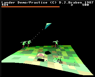
Red is used to change green into brown, so this gives the overall effect of a gentle green landscape that's pockmarked with small groups of red-brown dirt. This screenshot shows the effect reasonably clearly:
Having calculated the tile slope and the base colour, there is one more element to consider, and that's the tile row that we're on. We want tiles nearer the front of the landscape to be brighter than those at the back, to give a more three-dimensional depth to the landscape, so we need to include the corner row number in the calculation, which is in the range 1 to 10 (we don't calculate the tile colours for corner row 0 as we don't draw any tiles for the first row).
Bringing this all together, the final calculation for each channel of the tile colour is as follows:
colour = base colour + row number + (slope >> 22)
This value is calculated for each channel, before being capped and converted into a VIDC-compatible colour byte that's ready to be poked into screen memory (see the deep dive on screen memory in the Archimedes for more details on this process).
So the appearance of each tile is defined by the altitude of the front-right corner, the slope along the front edge of the tile, and the corner row of the front edge, such that:
- The launchpad is grey, the sea is blue, and the landscape is predominantly green but with brown patches
- Tiles that point to the left are brighter than tiles that point to the right
- Steeply sloping left-facing tiles are brighter than gently sloping tiles
- Tiles are brighter towards the front of the landscape than at the back
This approach helps to simulate the light source being above the landscape but slightly to the left, which is the same logic that's applied when drawing objects (see the deep dive on drawing 3D objects for more details of the game's lighting model).
And that is how the landscape is drawn in Lander, as rows of projected tile corners with colours that are based on slope, depth and altitude. As patchwork quilts go, it's quite a sophisticated bit of embroidery.